The printable version is no longer supported and may have rendering errors. Please update your browser bookmarks and please use the default browser print function instead.
The Nintendo Switch mainboard has a series of testpads on the front and back, presumably used in factory test, diagnostics, and early board bringup procedures.
Raw Logic captures
These are reference materials, taken from poking at I/O on various testpads. https://github.com/hedgeberg/Switch-Logic-Captures
Photos
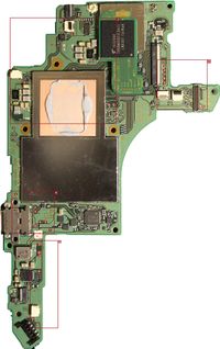
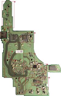
Pinouts
Cluster A
| Pad # |
Name |
Type |
Levels |
Continuity |
Frequency |
Comment
|
| 1 |
Batt GND? |
|
|
|
|
|
| 2 |
Battery pulse? |
Pulse train |
0-3.3V |
L-5? |
|
|
| 3 |
Battery Vdd |
|
|
|
|
|
| 4 |
Speaker R + |
Square wave |
0-3.3V |
|
|
Speaker Right +
|
| 5 |
Speaker R - |
Square wave |
0-3.3V |
|
|
Speaker Right -
|
| 6 |
Weak GND? |
|
|
|
|
|
| 7 |
SDA |
I2C |
0-1.8V |
|
|
I2C Port 0
|
| 8 |
SCL |
I2C |
0-1.8V |
|
|
I2C Port 0
|
| 9 |
USB-PWR-WAVE? |
Square wave |
0-3.3V |
K-4, K-5? |
~11 Hz |
|
| 10 |
USB-PWR-WAVE? |
Square wave |
0-3.3V |
K-4, K-5? |
~11 Hz |
|
Cluster B
| Pad # |
Name |
Type |
Levels |
Continuity |
Frequency |
Comment
|
| 1 |
|
DBVDD |
|
|
|
from ALC5639 pin 43
|
| 2 |
D+ |
USB-C |
|
|
|
Cluster B - 3
|
| 3 |
D- |
USB-C |
|
|
|
Cluster B - 2
|
| 4 |
+3.3V |
XRST |
|
|
|
from M92T36 pin 4
|
| 5 |
+3.3V |
VSVR |
|
|
|
from M92T36 pin 6
|
| 5(b) |
VUSB |
VB |
|
|
|
from M92T36 pin 9
|
| 6 |
GND |
|
|
|
|
|
Cluster C
| Pad # |
Name |
Type |
Levels |
Continuity |
Frequency |
Comment
|
| 1 |
?? |
|
0-1.8V |
|
|
No clue. This is definitely important, we just have no idea how. May need to interface with dock for comms.
|
| 2 |
UART-A RX |
|
0-1.8V |
|
|
UART input
|
| 3 |
UART-A TX |
|
0-1.8V |
|
|
UART output
|
| 4 |
?? |
|
0-1.8V |
|
|
|
| 5 |
?? |
|
0-1.8V |
|
|
|
| 6 |
UART-A RTS |
|
0-1.8V |
|
|
UART-A Flow control
|
| 7 |
?? |
|
0-1.8V |
|
|
|
| 8 |
UART-A CTS |
|
0-1.8V |
|
|
UART-A Flow control
|
| 9 |
?? |
|
0-1.8V |
|
|
|
| 10 |
?? |
|
0-1.8V |
|
|
|
| 11 |
+1.8V |
|
0-1.8V |
|
|
|
Cluster D
| Pad # |
Name |
Type |
Levels |
Continuity |
Frequency |
Comment
|
| 1 |
GND |
|
|
|
|
|
| 4 |
Seaker L + |
|
|
|
|
Speaker Left +
|
| 5 |
Seaker L - |
|
|
|
|
Speaker Left -
|
Cluster E
| Pad # |
Name |
Type |
Levels |
Continuity |
Frequency |
Comment
|
| 1 |
Vol (-) |
|
|
|
|
Button Vol (-)
|
| 10 |
Reset |
|
|
|
|
|
| 11 |
Power Button |
Pushbutton |
4V-0V |
|
|
Active low
|
Cluster G
| Pad # |
Name |
Type |
Levels |
Continuity |
Frequency |
Comment
|
| 1 |
SD card detect |
|
|
|
|
|
| 2 |
GND |
|
|
|
|
|
| 4 |
Vol(+) |
|
|
|
|
Button Vol (+)
|
| 5 |
Li-Ion Batt Vdd Mirror |
|
|
|
|
Power Supply
|
| 9 |
BUTTON_HOME |
|
|
|
|
RCM strap
|
Cluster H
| Pad # |
Name |
Type |
Levels |
Continuity |
Frequency |
Comment
|
| 1 |
|
|
|
|
|
|
| 2 |
|
|
|
|
|
|
| 3 |
|
|
|
|
|
|
| 4 |
Screen_on |
On/Off |
0-1.8v |
I-2 |
|
Screen power state, active high
|
| 5 |
|
Flow control |
0-1.8V |
I-5 |
Flow control for pad I-4? |
|
| 6 |
|
|
|
|
|
|
| 7 |
|
UART |
0-1.8V |
I-4 |
1.5MBaud? |
|
| 8 |
|
UART |
0-1.8V |
I-3 |
1.5MBaud? |
|
| 9 |
|
|
|
|
|
|
| 10 |
|
|
|
|
H-12 |
On the same trace
|
| 11 |
|
|
|
|
|
Goes to a small ceramic cap near WiFi/BT IC?
|
| 12 |
|
|
|
H-10 |
|
On the same trace
|
Cluster I
| Pad # |
Name |
Type |
Levels |
Continuity |
Frequency |
Comment
|
| 1 |
GND |
|
|
|
|
|
| 2 |
Screen_on |
On/Off |
0-1.8V |
|
|
Screen power state, active high
|
| 3 |
|
UART |
0-1.8V |
|
1.5MBaud? |
Communication CPU -> Bluetooth using HCI
|
| 4 |
|
UART |
0-1.8V |
|
1.5MBaud? |
Communication Bluetooth -> CPU using HCI
|
| 5 |
|
Flow control |
0-1.8V |
|
|
Flow control for pad I-4?
|
| 6 |
|
|
0-1.8V |
|
|
Needs testing with chip/touch screen interface board plugged in
|
Cluster J
| Pad # |
Name |
Type |
Levels |
Continuity |
Frequency |
Comment
|
| 1 |
? |
Edge |
0-1.8V |
|
|
Turns on around same time as pad J-3
|
| 2 |
GND |
|
|
|
|
|
| 3 |
? |
Edge |
0-1.8V |
|
|
Turns on around same time as pad J-1, slightly after
|
| 4 |
Power button |
Pushbutton |
4V-0V |
|
|
Active low
|
| 5 |
? |
Constant? |
0V |
Ground?-NT |
|
|
| 6 |
? |
Edge |
0-1.8V |
|
|
Turns on with pad J-6, ~1s after J-1/J-3
|
| 7 |
? |
Edge |
0-1.8V |
|
|
Turns on with pad J-5, ~1s after J-1/J-3
|
| 8 |
? |
Edge? |
0-1.8V |
|
|
Turns on ~1s after J-6/J-7, turns off at unknown point
|
Cluster K
| Pad # |
Name |
Type |
Levels |
Continuity |
Frequency |
Comment
|
| 1 |
GND |
|
|
|
|
|
| 2 |
D- |
USB-C |
|
|
|
Cluster B - 3
|
| 3 |
D+ |
USB-C |
|
|
|
Cluster B - 2
|
| 4 |
USB-PWR-WAVE? |
Square wave |
0V-3.3V |
A-9, A-10? |
~11 Hz |
|
| 5 |
USB-PWR-WAVE? |
Square wave |
0V-3.3V |
A-9, A-10? |
~11 Hz |
Appears to mirror K4. Duty cycle 66.67%. Low on screen lock. Off until first interaction.
|
| 6 |
USB-C V+ |
Supply power |
|
|
|
support fast charger : "normal mode = 5V+" "Fast changer = 12V+"
|
| 7 |
BQ24193 VBUS + M92T36 VEX |
Power supply? |
~3V-0V |
None known |
N/A |
0 when usb-c not plugged in, falls slowly on first interaction if USB-C plugged in. Power draw related?
|
Cluster L
TODO: Update diagram
| Pad # |
Name |
Type |
Levels |
Continuity |
Frequency |
Comment
|
| 1 |
Li-Ion Batt Vdd Mirror |
Power Supply |
Std. Li-Ion |
|
|
|
| 2 |
GND |
|
|
|
|
|
| 3 |
Li-Ion Batt Vdd |
Battery Input |
Std. Li-Ion |
|
|
|
| 4 |
Mirrored Ground? |
|
|
|
|
Holds steady @ 0, looks like a decoupled isolated ground
|
| 5 |
Battery pulse? |
|
|
|
<1 Hz |
Duty cycle ~0%
|
| 6 |
GND |
|
|
|
|
|

