The Nintendo Switch mainboard has a series of testpads on the front and back, presumably used in factory test, diagnostics, and early board bringup procedures.
Raw Logic captures
These are reference materials, taken from poking at I/O on various testpads. https://github.com/hedgeberg/Switch-Logic-Captures
Photos
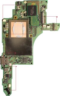
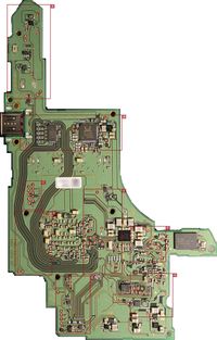
Pinouts
Cluster A
| Pad # |
Name |
Type |
Levels |
Continuity |
Frequency |
Comment
|
| 1 |
Batt GND? |
|
|
|
|
|
| 2 |
Battery pulse? |
Pulse train |
0-3.3V |
L-5? |
|
|
| 3 |
Battery Vdd |
|
|
|
|
|
| 4 |
Speaker R + |
Square wave |
0-3.3V |
|
|
Speaker Right +
|
| 5 |
Speaker R - |
Square wave |
0-3.3V |
|
|
Speaker Right -
|
| 6 |
Weak GND? |
|
|
|
|
|
| 7 |
SDA |
I2C |
0-1.8V |
|
|
|
| 8 |
SCL |
I2C |
0-1.8V |
|
|
|
| 9 |
USB-PWR-WAVE? |
Square wave |
0-3.3V |
K-4, K-5? |
~11 Hz |
|
| 10 |
USB-PWR-WAVE? |
Square wave |
0-3.3V |
K-4, K-5? |
~11 Hz |
|
Cluster B
| Pad # |
Name |
Type |
Levels |
Continuity |
Frequency |
Comment
|
| 1 |
|
DBVDD |
|
|
|
from ALC5639 pin 43
|
| 2 |
D+ |
USB-C |
|
|
|
Cluster B - 3
|
| 3 |
D- |
USB-C |
|
|
|
Cluster B - 2
|
| 4 |
+3.3V |
XRST |
|
|
|
from M92T36 pin 4
|
| 5 |
+3.3V |
VSVR |
|
|
|
from M92T36 pin 6
|
| 5(b) |
VUSB |
VB |
|
|
|
from M92T36 pin 9
|
| 6 |
GND |
|
|
|
|
|
Cluster C
| Pad # |
Name |
Type |
Levels |
Continuity |
Frequency |
Comment
|
| 1 |
?? |
|
0-1.8V |
|
|
No clue. This is definitely important, we just have no idea how. May need to interface with dock for comms.
|
| 2 |
UART-A RX |
|
0-1.8V |
|
|
UART input
|
| 3 |
UART-A TX |
|
0-1.8V |
|
|
UART output
|
| 4 |
?? |
|
0-1.8V |
|
|
|
| 5 |
?? |
|
0-1.8V |
|
|
|
| 6 |
UART-A RTS |
|
0-1.8V |
|
|
UART-A Flow control
|
| 7 |
?? |
|
0-1.8V |
|
|
|
| 8 |
UART-A CTS |
|
0-1.8V |
|
|
UART-A Flow control
|
| 9 |
?? |
|
0-1.8V |
|
|
|
| 10 |
?? |
|
0-1.8V |
|
|
|
| 11 |
+1.8V |
|
0-1.8V |
|
|
|
Cluster D
| Pad # |
Name |
Type |
Levels |
Continuity |
Frequency |
Comment
|
| 1 |
GND |
|
|
|
|
|
| 4 |
Seaker L + |
|
|
|
|
Speaker Left +
|
| 5 |
Seaker L - |
|
|
|
|
Speaker Left -
|
Cluster E
| Pad # |
Name |
Type |
Levels |
Continuity |
Frequency |
Comment
|
| 1 |
Vol (-) |
|
|
|
|
Button Vol (-)
|
| 10 |
Reset |
|
|
|
|
|
| 11 |
Vdd Referance |
|
|
|
|
|
Cluster G
| Pad # |
Name |
Type |
Levels |
Continuity |
Frequency |
Comment
|
| 2 |
GND |
|
|
|
|
|
| 4 |
Vol(+) |
|
|
|
|
Button Vol (+)
|
| 5 |
Li-Ion Batt Vdd Mirror |
|
|
|
|
Power Supply
|
| 9 |
BUTTON_HOME |
|
|
|
|
RCM strap
|
Cluster H
| Pad # |
Name |
Type |
Levels |
Continuity |
Frequency |
Comment
|
| 1 |
|
|
|
|
|
|
| 2 |
|
|
|
|
|
|
| 3 |
|
|
|
|
|
|
| 4 |
Screen_on |
On/Off |
0-1.8v |
I-2 |
|
Screen power state, active high
|
| 5 |
|
Flow control |
0-1.8V |
I-5 |
Flow control for pad I-4? |
|
| 6 |
|
|
|
|
|
|
| 7 |
|
UART |
0-1.8V |
I-4 |
1.5MBaud? |
|
| 8 |
|
UART |
0-1.8V |
I-3 |
1.5MBaud? |
|
| 9 |
|
|
|
|
|
|
| 10 |
|
|
|
|
H-12 |
On the same trace
|
| 11 |
|
|
|
|
|
Goes to a small ceramic cap near WiFi/BT IC?
|
| 12 |
|
|
|
H-10 |
|
On the same trace
|
Cluster I
| Pad # |
Name |
Type |
Levels |
Continuity |
Frequency |
Comment
|
| 1 |
GND |
|
|
|
|
|
| 2 |
Screen_on |
On/Off |
0-1.8V |
|
|
Screen power state, active high
|
| 3 |
|
UART |
0-1.8V |
|
1.5MBaud? |
|
| 4 |
|
UART |
0-1.8V |
|
1.5MBaud? |
|
| 5 |
|
Flow control |
0-1.8V |
|
|
Flow control for pad I-4?
|
| 6 |
|
|
0-1.8V |
|
|
Needs testing with chip/touch screen interface board plugged in
|
Cluster J
| Pad # |
Name |
Type |
Levels |
Continuity |
Frequency |
Comment
|
| 1 |
? |
Edge |
0-1.8V |
|
|
Turns on around same time as pad J-3
|
| 2 |
GND |
|
|
|
|
|
| 3 |
? |
Edge |
0-1.8V |
|
|
Turns on around same time as pad J-1, slightly after
|
| 4 |
Power button |
Pushbutton |
4V-0V |
|
|
Active low
|
| 5 |
? |
Constant? |
0V |
Ground?-NT |
|
|
| 6 |
? |
Edge |
0-1.8V |
|
|
Turns on with pad J-6, ~1s after J-1/J-3
|
| 7 |
? |
Edge |
0-1.8V |
|
|
Turns on with pad J-5, ~1s after J-1/J-3
|
| 8 |
? |
Edge? |
0-1.8V |
|
|
Turns on ~1s after J-6/J-7, turns off at unknown point
|
Cluster K
| Pad # |
Name |
Type |
Levels |
Continuity |
Frequency |
Comment
|
| 1 |
GND |
|
|
|
|
|
| 2 |
D- |
USB-C |
|
|
|
Cluster B - 3
|
| 3 |
D+ |
USB-C |
|
|
|
Cluster B - 2
|
| 4 |
USB-PWR-WAVE? |
Square wave |
0V-3.3V |
A-9, A-10? |
~11 Hz |
|
| 5 |
USB-PWR-WAVE? |
Square wave |
0V-3.3V |
A-9, A-10? |
~11 Hz |
Appears to mirror K4. Duty cycle 66.67%. Low on screen lock. Off until first interaction.
|
| 6 |
USB-C V+ |
Supply power |
|
|
|
support fast charger : "normal mode = 5V+" "Fast changer = 12V+"
|
| 7 |
BQ24193 VBUS + M92T36 VEX |
Power supply? |
~3V-0V |
None known |
N/A |
0 when usb-c not plugged in, falls slowly on first interaction if USB-C plugged in. Power draw related?
|
Cluster L
TODO: Update diagram
| Pad # |
Name |
Type |
Levels |
Continuity |
Frequency |
Comment
|
| 1 |
Li-Ion Batt Vdd Mirror |
Power Supply |
Std. Li-Ion |
|
|
|
| 2 |
GND |
|
|
|
|
|
| 3 |
Li-Ion Batt Vdd |
Battery Input |
Std. Li-Ion |
|
|
|
| 4 |
Mirrored Ground? |
|
|
|
|
Holds steady @ 0, looks like a decoupled isolated ground
|
| 5 |
Battery pulse? |
|
|
|
<1 Hz |
Duty cycle ~0%
|
| 6 |
GND |
|
|
|
|
|

